For lunch, do you enjoy having your tomato whole, in slices or finely chopped? It probably depends on the dish: The tomato could serve as a standalone fruit snack, as part of a sandwich or as a salad topping. Similarly, different Fermilab experiments may want particles beams coming to them in different chunks. Now they have a chopping “knife” to prepare the beam to their taste: the new beam chopper for the future Fermilab linear accelerator.
Scientists can create custom particle beams by removing select particle bunches — or packets of particles each containing about 200 million particles — from a longer, continuous queue. For example, experts can adjust settings to eject every third bunch, with the remaining bunches forming a particular pattern that’s optimized for an experiment. The beam chopper is the device that carries out this high-precision bunch removal.
Beam choppers are ubiquitous in ion accelerators. But when, several years ago, a team of Fermilab accelerator experts set out to design the chopper that would become part of the lab’s upgraded accelerator complex, nothing even close to what was needed existed.
The program of upgrades called Proton Improvement Plan-II (PIP-II) will meet the demands of Fermilab’s future experiments for more and more intense particle beams. While the new PIP-II linear accelerator uses superconducting resonators to increase the particles energy to 800 million electronvolts, the chopper is placed upstream in the section called the medium-energy beam transport, MEBT. It will pass for acceleration only those bunches that are requested by the experiments and remove all others.
A beam chopper has two main parts: kicker and absorber. The kicker removes unneeded bunches. The absorber receives them.
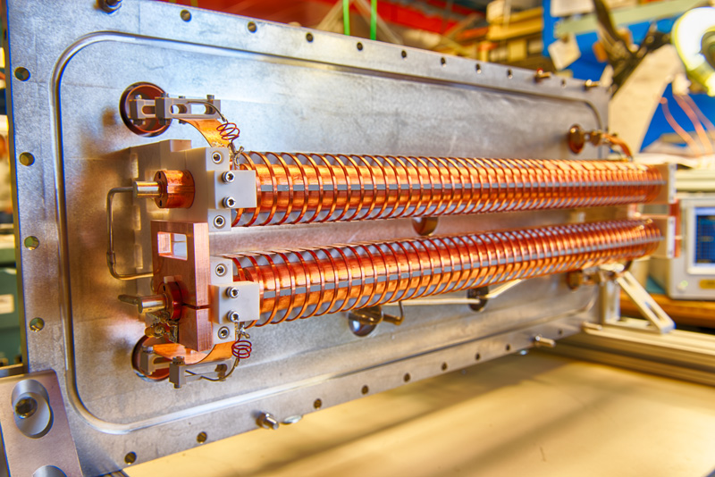
The kicker is essentially two parallel plates between which voltage can change quickly, and it is situated at an optimal point in the beam path for bunch removal. So when a bunch to be removed flies between the kicker plates, a voltage is applied — a nanosecond-long, roughly 1,000-volt burst of electric potential. That pulse kicks the bunch out of the main queue and into the beam absorber downstream.
PIP-II asks a great deal of the chopper. The MEBT chopper must act rapidly, able to remove bunches at a high frequency. It must be able to generate a pulse strong enough to completely eject entire bunches. It has to be precise enough to pick off single bunches without perturbing its neighbors — removing the unneeded bunches and only the unneeded bunches. The propagation of the voltage through the kicker plates has to sync perfectly with the path of the hydrogen ion bunches. And with record-power ion beams barreling through the accelerator, the chopper must be hardy enough to handle the increased power and radiation.
It was a collection of demands beyond the current state of the art.
The Fermilab accelerator team experimented with various designs, timings, electromagnetic variables and beam parameters. They developed two different kicker prototypes — a 50-ohm and a 200-ohm kicker, each requiring a specific way to create the electric signal. For example, the 200-ohm version would use a switch: open the switch and close it quickly back, and a short voltage pulse runs into the kicker. (It is almost like making a flash of the light by pushing a button of your flashlight, except the voltage is more than 100 times higher and “pushing” needs to be done in a billionth of second, tens of millions times per second.)
Ding Sun began development, prototyping, and eventually testing of the 50-ohm kicker version. Greg Saewert led the development of both the 200-ohm kicker and its switch driver, later joined by Daniil Frolov. Alex Chen led the mechanical design of both kicker versions.
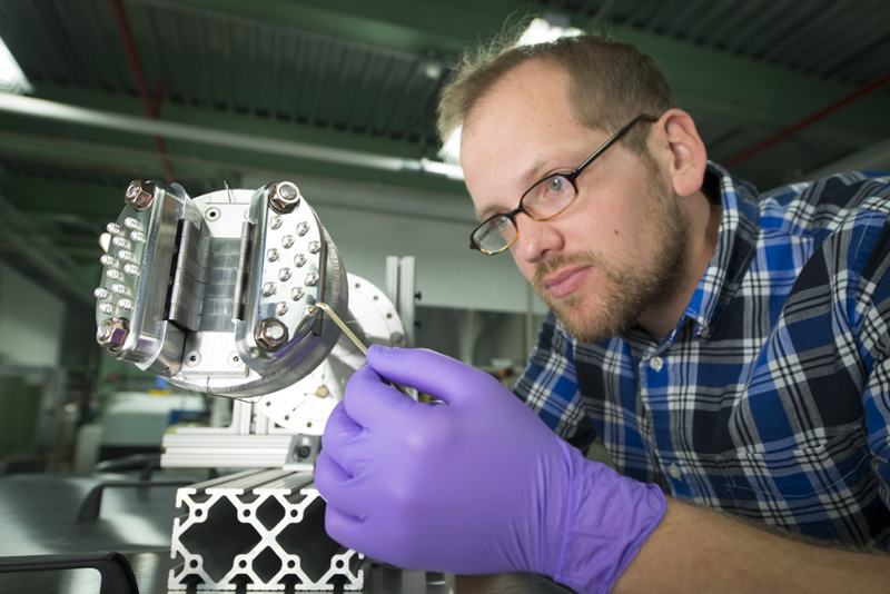
Even with kickers redefining the state-of-the-art and combining deflection of two of them, the orientation and size of the beam are such that there was not much room to negotiate the placement of the absorber, which would have to deal with a high power density from the beam. The absorber is a piece of metal that intercepts the removed portion of the beam. Curtis Baffes sketched contours of the future absorber and then made a quarter-size prototype. Of course, the rapid expansion of the absorber material under fast heating from the tightly focused beam was the biggest issue. Eventually, the team came up with a workable design, and another quarter-size prototype was successfully tested to maximum power density envisioned for the future accelerator, ready to be exposed to ions.
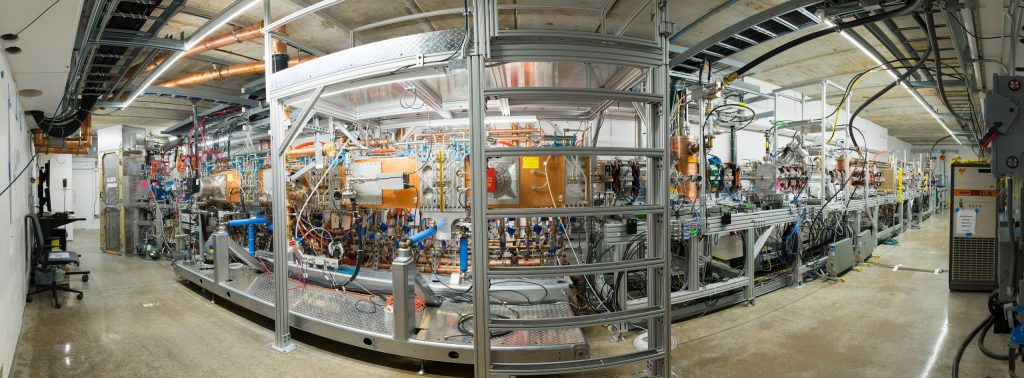
The PIP-II beam chopper will eventually be installed in the front end of this accelerator, called the PIP-II Injector Test accelerator, or PIP2IT. Photo: Reidar Hahn
Their final PIP-II chopper design comprised two kickers of the same type and one absorber. Each kicker fires as the unneeded bunch flies through the first and then the next, deflecting the bunch from the main beam. The absorber, like an outfielder on a baseball team, readily receives these high-frequency, high-power bunches.
When tests of the chopper components were conducted, to everybody’s excitement, several instruments showed how the beam envelope was splitting into two distinctive trajectories! Then, remove one of them, and a monitor downstream showed a sequence of bunches selected according to a predetermined pattern.
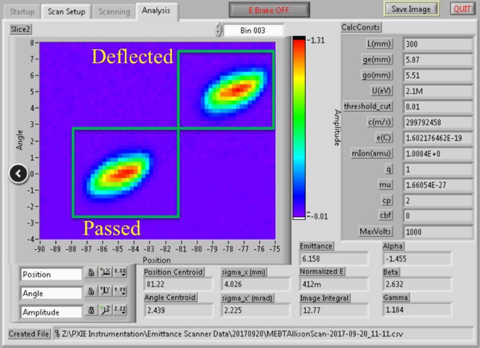
This screenshot shows an analysis of the beam properties in vertical direction. The vertical axis is the ions’ angle, and the horizontal axis is their position. Two trajectories are clearly separated when the kicker is deflecting every other bunch. Image courtesy of Alexander Shemyakin
The excitement was followed by multiple shifts answering multiple questions. Does each kicker deflect the beam as expected? Does the velocity of electric pulse propagation through the kicker match the ion speed? Can the deflections by two kickers be efficiently summed? Do kickers survive if the beam is passed through them for a day? Does the absorber prototype behave with the ion beam as it was predicted from experiments with electrons? Each “yes” was adding confidence that the chopper will work, and heart of future PIP-II can beat as it has been envisioned eight years ago.
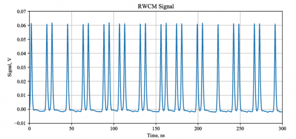
This waveform shows part of the bunch pattern tailored for Booster injection created by the 200-ohm kicker. Image courtesy of Daniil Frolov
In 2018, the team plans to demonstrate operation of PIP2IT with a high-power beam, manufacture and install a full-size absorber, and order two final-design kickers, which will be slightly modified version of the present 200 Ohm kicker. In a year or so, the team hopes to have a chopper capable of fulfilling the first tasks foreseen for PIP-II, injection into the Booster and supplying the beam for the upgraded version of the Mu2e experiment.
Learn more in proceedings from the recent HB2018 conference or from a recent IEEE conference.

